
Where should material remain?
We redistribute a limited amount of material using Floating Projection Topology Optimization, or FPTO, which extracts a smooth boundary from the numerical design.
Research highlight · Additive manufacturing
When a printed material is stronger in one direction than another, choosing where to put it is not enough. We also need to choose which way it points.
Published in Finite Elements in Analysis & Design (FEAD) · 2026
Read the open-access paper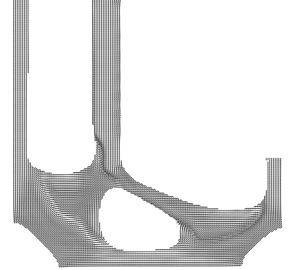
The motivation
Topology optimization finds where material is most useful, often producing intricate shapes with branches and openings that are difficult to manufacture conventionally. Additive manufacturing, or 3D printing, is a major route for turning these optimized designs into real parts.
Yet the printing process also changes how those parts behave. Depositing material in layers and along particular paths can make a part stiffer or stronger in one direction than another, even when the starting material has no preferred direction. This effect is especially pronounced in extrusion-based printing and with fibre-reinforced filaments. Engineers call this directional behaviour anisotropy. Think of wood: loading along its grain is not the same as loading across it.
Many standard topology-optimization models assume that material behaves identically in every direction. If we use that assumption to design a printed part, we can overlook the directional stiffness and strength introduced by manufacturing. A shape that looks efficient in the model may behave differently once printed.
We bring that manufacturing reality into the design problem. In this work, we optimize the shape and local printing directions together, while enforcing a strength condition throughout the optimization. We ask not only where material should go, but which way it should point and whether it can carry the load.
Who led the work
Lead author
Bruno led this research at SSI Lab, working with Aldemar Siqueira, Xiaodong Huang and Josué Labaki to bring shape, printing direction and anisotropic strength into a single optimization problem.
He is now pursuing a PhD at York University in Toronto, Canada.
Bruno on LinkedInWe redistribute a limited amount of material using Floating Projection Topology Optimization, or FPTO, which extracts a smooth boundary from the numerical design.
We update local material directions alongside the shape, so the directional material can work with the routes through which the structure carries load.
We use the Tsai–Wu criterion to account for directional strengths and the interaction of stresses. A smooth aggregate lets us handle the many local failure checks together.
Inside the paper · L-bracket benchmark
The L-shaped bracket is a demanding test because stress tends to concentrate near its inside corner. We compare two designs under the same loads and supports, using the same directional material and a target volume fraction of 50%. We include the failure constraint in both designs.
Shape only · printing direction fixed
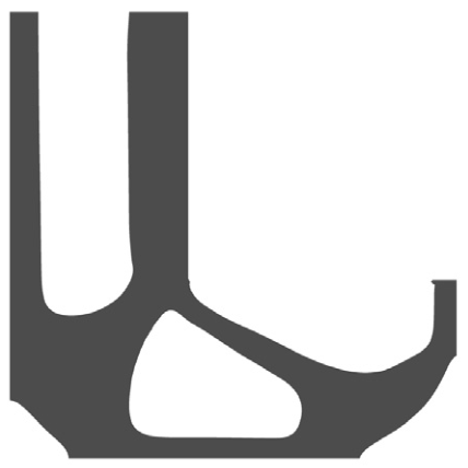
Compliance25.1698
Shape + local printing direction
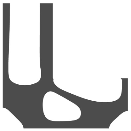
Compliance15.0192
Compliance is the load-weighted displacement of a structure, written C = Fᵀu. With the load F held fixed, a smaller value means less deformation in the directions in which the forces act. It measures stiffness, not the margin against every possible form of failure.
Why the strength check matters
In a third calculation, we removed the failure constraint while keeping the loading and material budget. We obtained a design with a sharp inner corner: a concentrated load path that looks efficient for stiffness but creates a critical stress concentration.
When we include the failure constraint, our method reshapes that region to reduce the concentration. We can therefore balance stiffness and material direction with the strength requirement, instead of accepting a shape on stiffness alone.

What the evidence establishes
We tested our formulation on an L-bracket, a cantilever and an MBB beam. We used plane-stress models and in-plane material directions, relevant to planar deposition of reinforcing fibres.
Our results are numerical demonstrations. To assess fatigue life, interlayer performance and printer-specific manufacturing constraints, we would need additional models and tests of printed components.
When manufacturing gives a material direction-dependent properties, we need to design with those properties from the start. Our work brings that direction into the optimization, alongside shape and strength.
The paper
Bruno Benegra Denadai, Aldemar Siqueira, Xiaodong Huang and Josué Labaki.
Finite Elements in Analysis & Design 258 (2026), 104573.
Figures 4a, 4c, 7a and 8a reproduced from Denadai et al. (2026) under CC BY 4.0. Panels cropped from the original paper; numerical geometry and directions are unchanged. Explanatory text by SSI Lab.